PART 1:
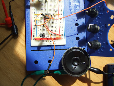
This experiment sets the 555 up in astable mode (check out the previous post for an explanation). The 555 will emit pulses at a certain frequency which will drive the speaker. Changing the frequency of the pulses will then in turn change the frequency of the speaker's tone. To change the pulse frequency or rate, we adjust the external capacitor connected to pin 6, the threshold pin. (or the resistor between 6 & 7)
 |
| From MAKE: Electronics: Experiment 17 (555 in astable mode) |
 |
| From MAKE: Electronics: Experiment 17 (555 in astable mode) |
Here's the circuit, lets have a look at the schematic of the 555 in astable mode again:
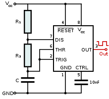
So the THRESHOLD is connected to the TRIGGER, when the cap, C, is charged past 2/3 of the Vsupply the threshold is passed and the capacitor discharges through R2 into pin 7 (DISCHARGE) and a pulse is emitted from OUT. Once the cap has discharged and the IC is no longer triggered, the cap starts charging again, when it reaches 2/3 Vsupply it repeats the process, this results in a series of pulses, this is called a square wave oscillator, because it's producing a a series of square wave pulses. This is great for generating tones on speakers, flashing LEDs (albeit highly overkill!) etc.
PART 2:
Now we chain 2 chips together, both in astable mode, this produces a warbling tone.
The 555 on the left (IC2) is working in the same way as in part 1, however this time, a second 555 (IC1) is chained to the chip with it's output attached to pin 5 of the tone generator 555 (IC2). When IC1 produces a pulse it increases the voltage at pin 5 (2/3 Vsupply results in the chip emitting a pulse) so when IC1 emits a pulse and triggers the second chip to generate a pulse the capacitor attached to pin 5 of IC2 is less charged than it would have been if IC1 wasn't chained to IC2, this results in a higher pitch, because IC1 is oscillating far slower than IC2, IC2 isn't always triggered by a pulse from IC1 meaning it operates in its normal mode and produces a lower frequency tone.
This results in a warbling sound to be produced as some of the time IC2 is producing high frequency square waves (when IC1 is emitting a pulse) and some of the time IC2 is producing lower frequency square waves (when IC1 is not emitting a pulse)
(the video shows the circuit the other way round, sorry about that!)
There is a hell of a lot of info in this experiment so I think I'll spend some time playing around with the 555 trying to figure out how to get it to emit different pulses, an oscilloscope would be great to have around for this experiment!