(this video is showing how the relay is wired up, once the sensor circuit is broken (open) the relay energises, when the sensor circuit is closed, the relay stays energised)
Part 1: Stripboard Layout:
This experiment calls for a protoboard in the same layout of a breadboard, which does seem a great way to introduce beginners to transferring projects from solderless breadboard to permanent perfboard. However I found this nigh on impossible to find in the UK. I settled using a perfboard and arranging the layout in a somewhat similar manner to a breadboard.
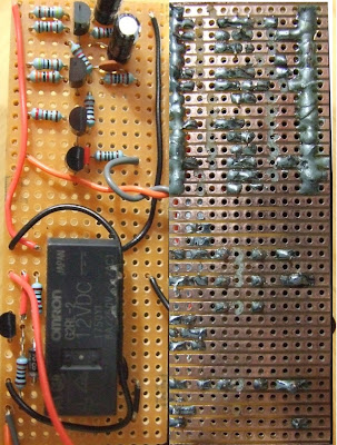
The picture shows the top side and under side of the board, I have mirrored the photograph so the top right of the up side = the top right of the under side, basically, you can overlay the pictures over each other as they correspond (I'm not really sure how to say this more clearly!)
 |
| From MAKE Electronics: Experiment 15: Burglar Alarm |
At the top of the board is the alarm circuit created back in experiment 11. At the bottom is a circuit that when triggered by an opening in the sensor circuit (i.e. opening a door) turns power on to the alarm circuit. If the sensor circuit is then closed again (door closed) power is still supplied to the alarm so it does not turn off. This is explained exceptionally well in the book however I think I only truly appreciated how the circuit worked when making my own (far less elegant) arrangement on a breadboard to see how it all worked from the schematic diagram.
I soldered everything on the stripboard first, then I took a dremel to it with a cutting wheel and trimmed it down and then sanded the sides, it fits in just between the slots in the project box so I don't have to screw it down (very convenient!).
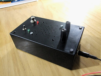
Part 2: Project Box
The point of this experiment is to show how one goes from a fairly minimalist circuit on the breadboard to a fully-fledged project. This requires casing to maintain the longevity of the project and also somewhere to mount a user interface. The UI for this project is fairly simple, it consists of:
(i) An Arming button - arms the alarm (and lights green LED to indicate the alarm is armed)
(ii) A Test button - (un-armed) lights up LED when sensor circuit is close, (armed) tests alarm circuit/speaker
I added some banana plugs to my magnetic sensor, I currently don't have anywhere to put it, Platt says later in the book that I'll learn how to integrate an 'away from home' feature and add a keypad to it (Hopefully I can figure out how to use a matrix keypad instead of a common pin type keypad) So I might get round to using it pending on how well it turns out. When activated the alarm isn't exactly loud so I will build an amplifier circuit at some point (I tried driving it with an old amp and it goes fairly loud for its size, it can certainly be ear piercing)